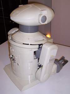
| Omnibot ® 2000 - Dissassembly Procedure |
This Robot has IC's and Transistors and are of the earlier designs. Static discharge can damage the electronics. It is recommended that you have and use a Static grounding wrist strap.
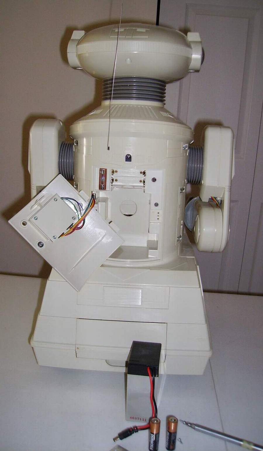
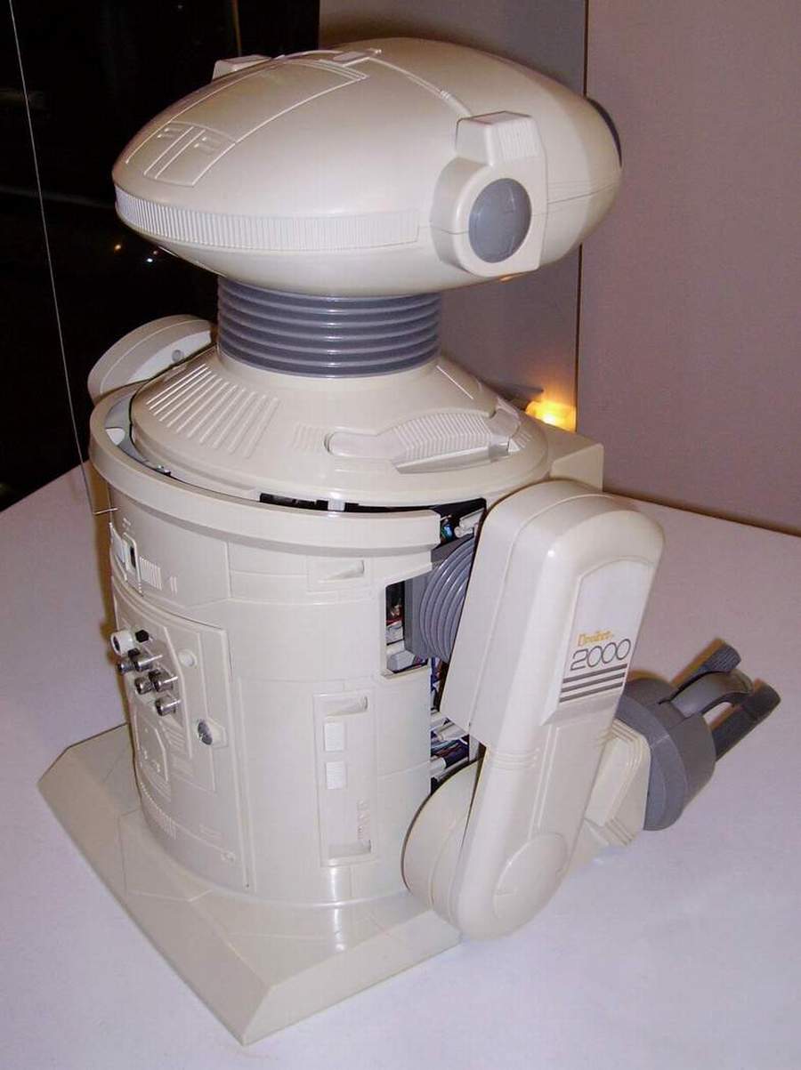
1. Make sure the robot is shut off. Open the rear door and remove the battery retainer and the large 6 V 4 AH DC rechargeable battery and the two small AA battery's. Close the door. |

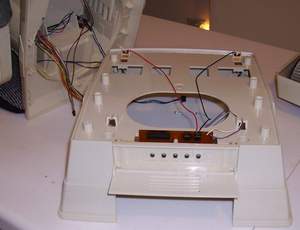
2. Turn the robot on to his back make sure that the head is free and not supporting the robot, then remove the six screws from the bottom of the robot keeping the base and housing together.
Keep these longer screws seperate to reinstall the base. |
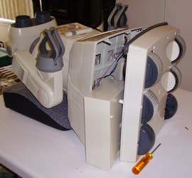
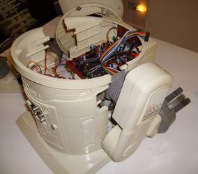
3. Separate the bottom base slowly from the housing and remove the draw from the robot. |
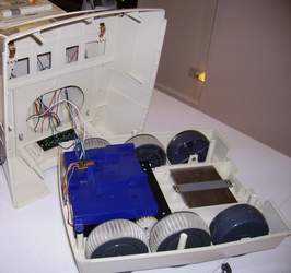
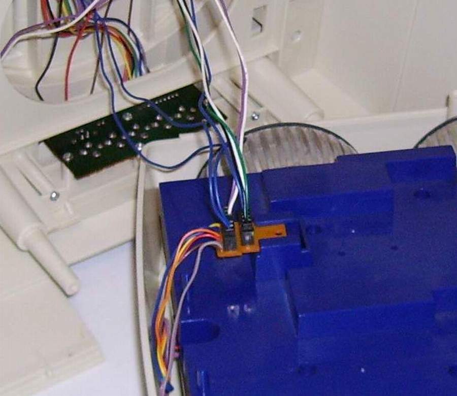
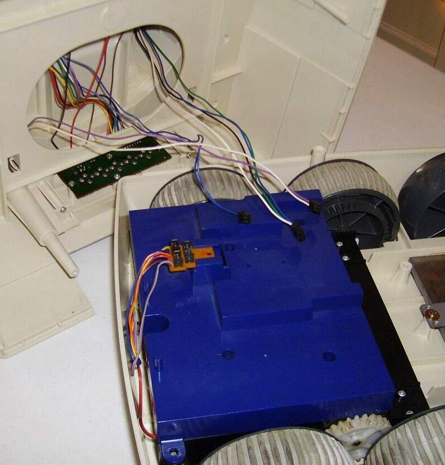
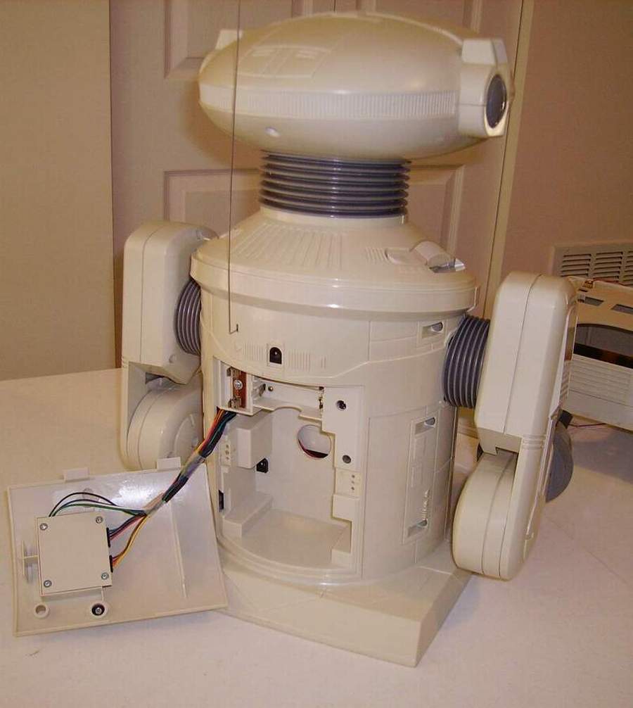
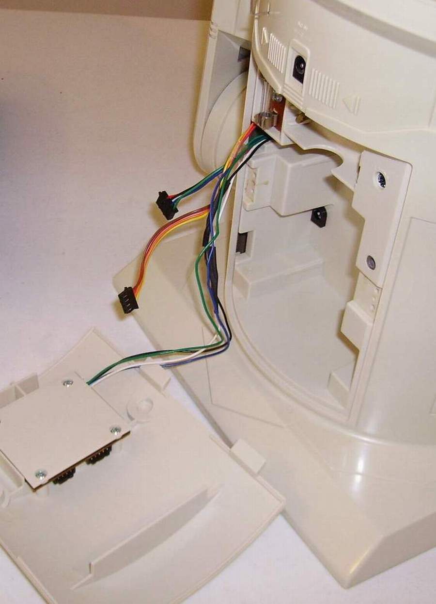
4. Turn the base and unplug the three plugs from the drive box that go to the robot. Make sure that you record where the plugs go. |
 |
 |
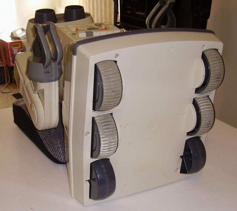
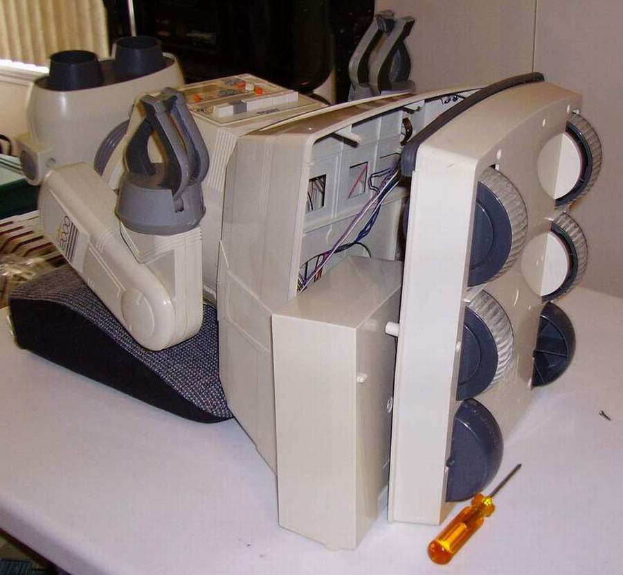
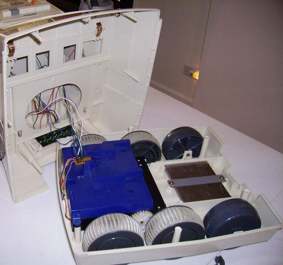
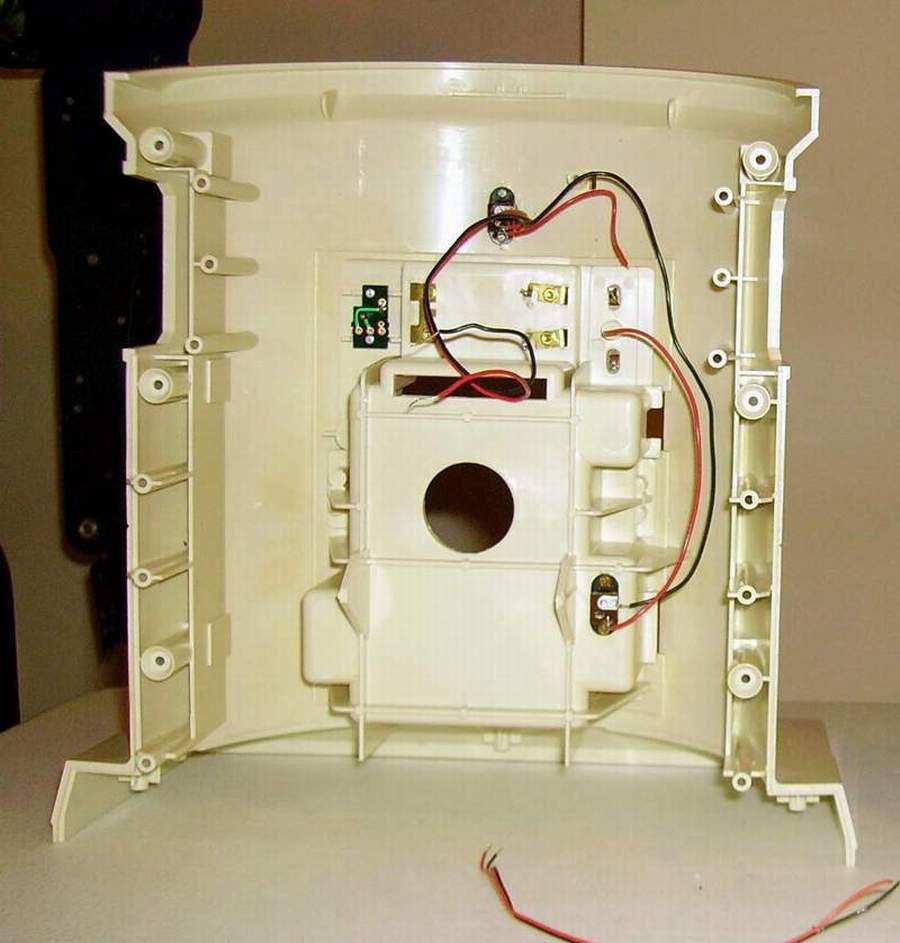
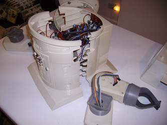
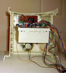
5. Remove the screws from the base housing of the robot. With wires still attached, seperate the base housing from the robot, turn it and lay it flat on the table. Do not try to remove it yet. |
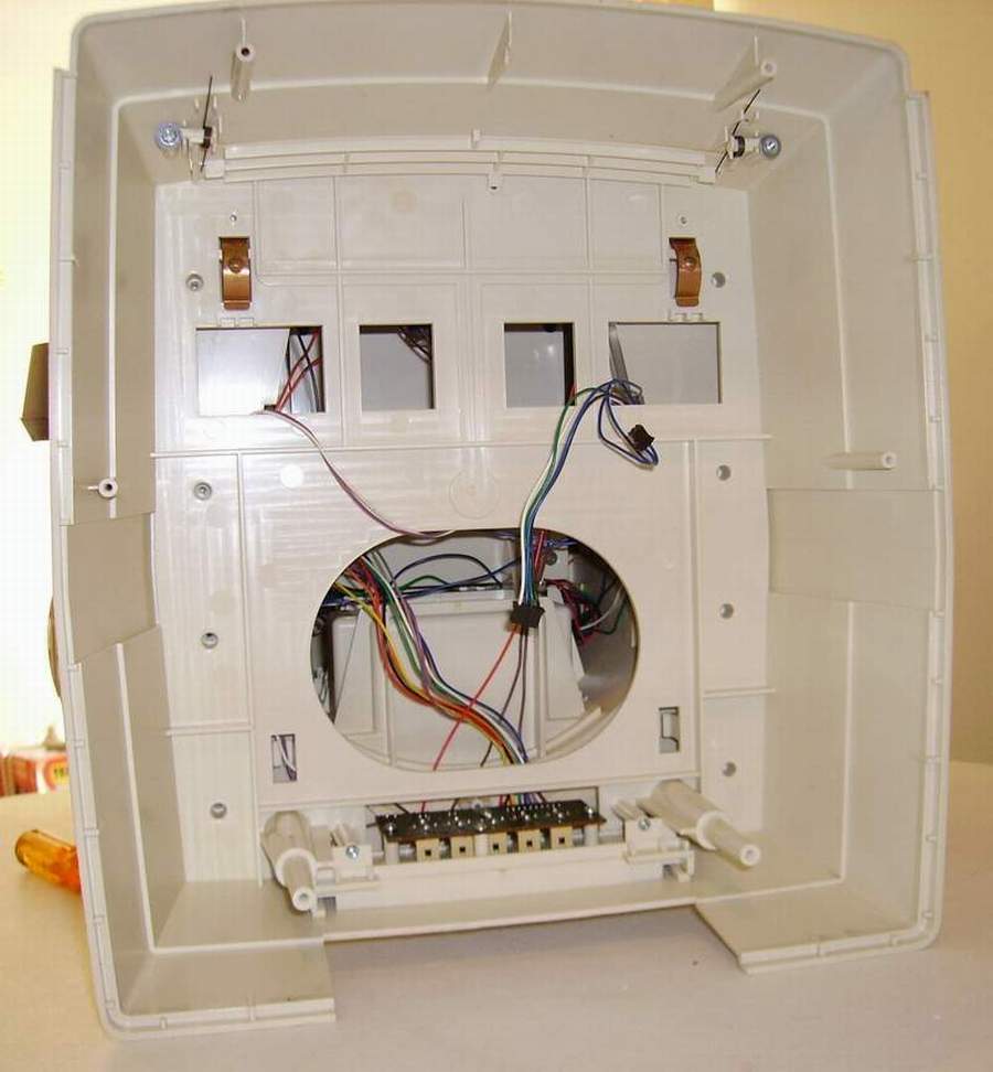
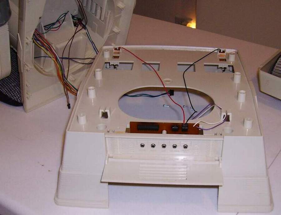
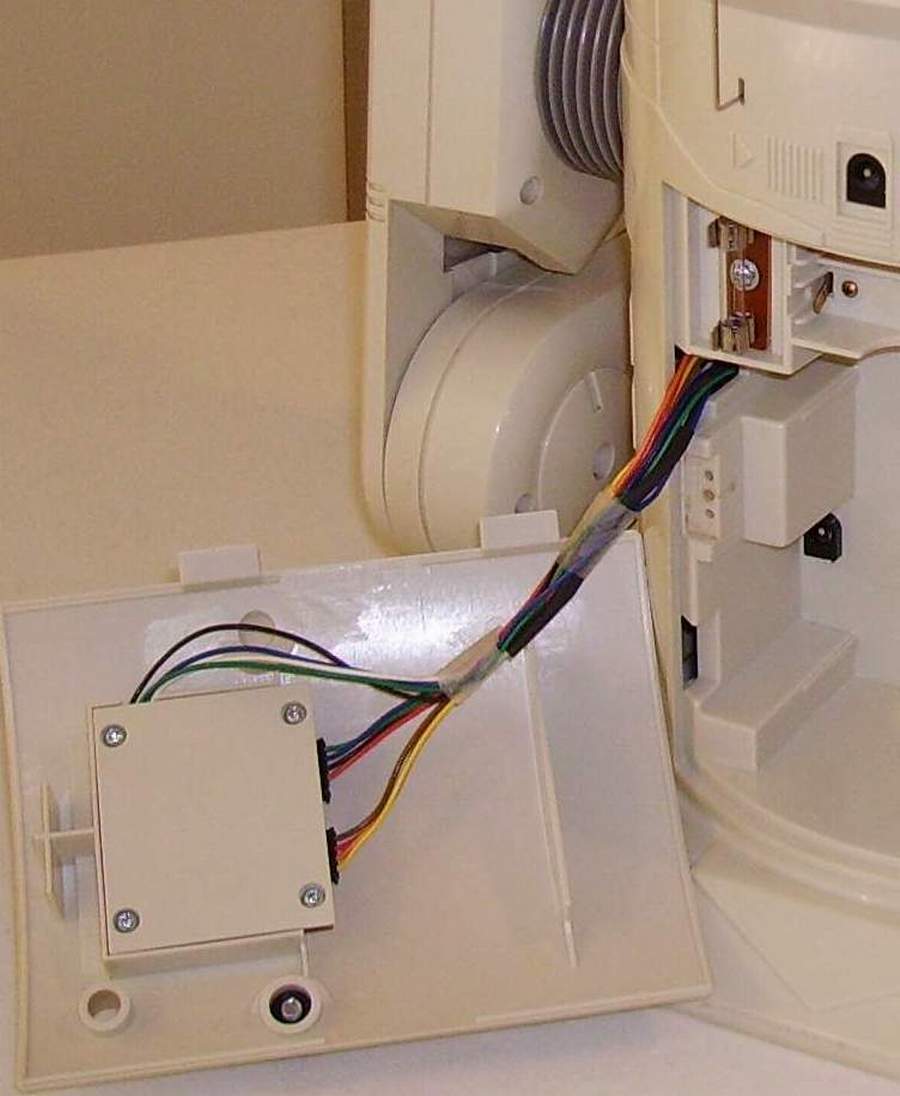
6. Leave the wires for the tray and remove the wires and plugs that go to the external Jacks board on the base housing from the robot.
7. Remove the base housing from the robot. |
* ( ANTENNA - If your robot has a base antenna you have to detach it at this stage.)
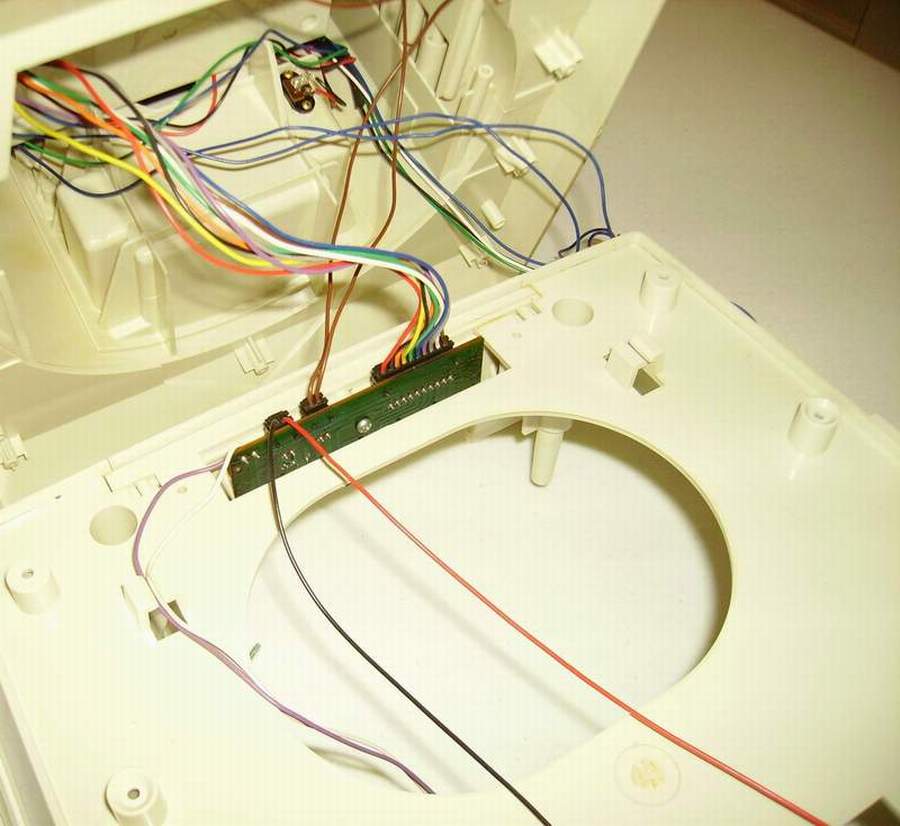
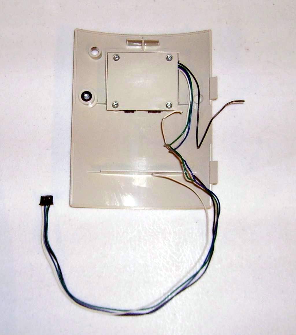
8. Open the rear door and remove the two plugs from the accessories interface board on the door. These two plugs and harness will have to be pushed into the robot. Close the door.
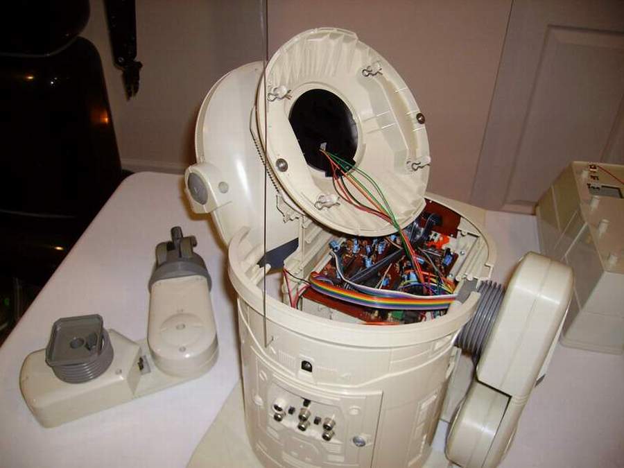
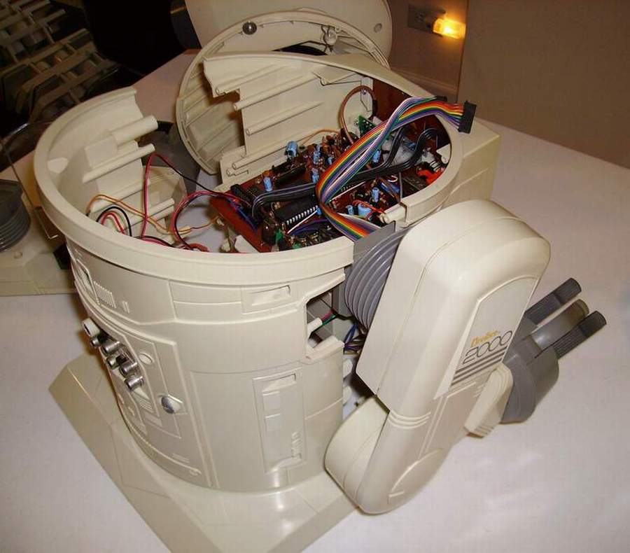
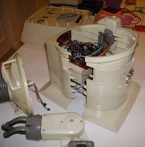
9. Remove the six screws from the back of the robot, and spread it apart slowly and very little (1 inch). (BE CAREFUL) |

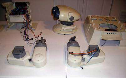
10. Spread the body apart just far enough to remove the left arm, put it down, and lift the head out. The robot back is still attached to the front by the wiring and the right arm can slip out and fall (BE CAREFUL) |
11. Un-plug the head from the circuit board, two plugs, and put the head down. |
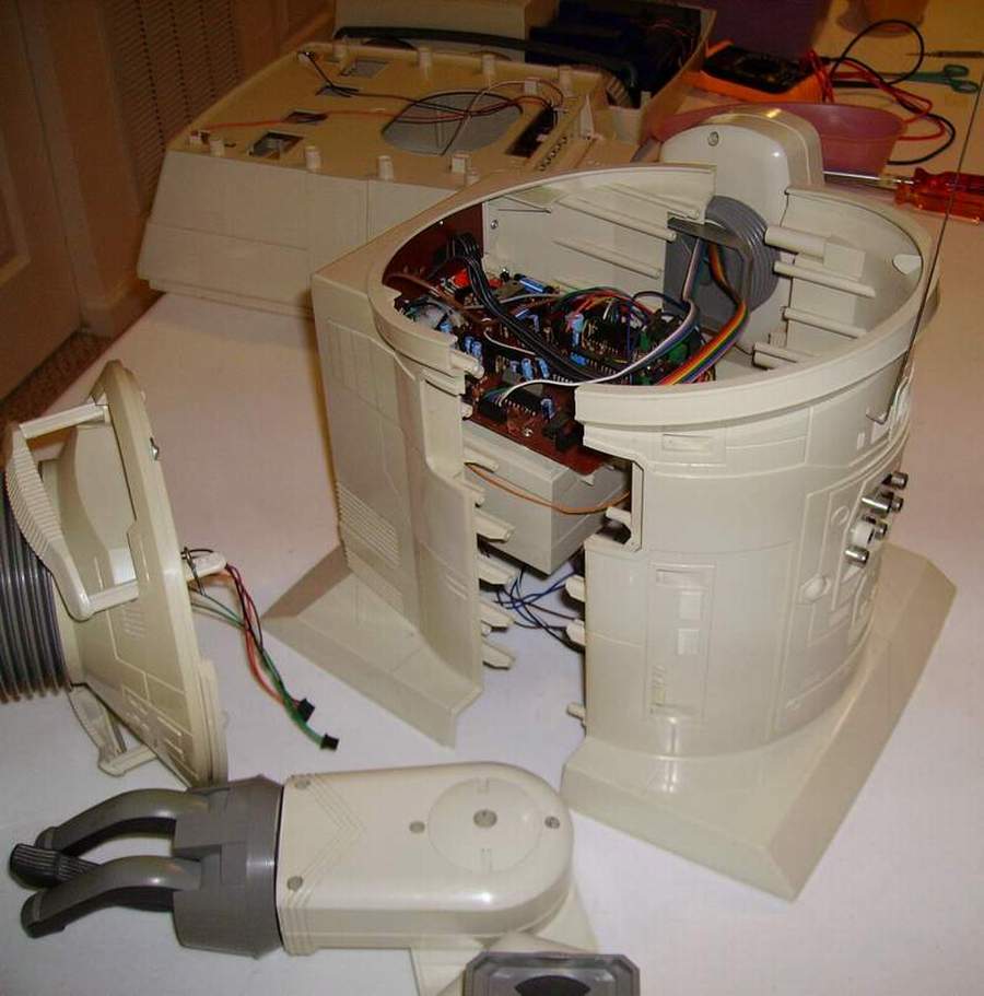
12. Un-plug the right arm cables from the circuit board, two cables and plugs. |
 |
13. Remove the right arm from the body and put it down. |
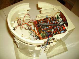
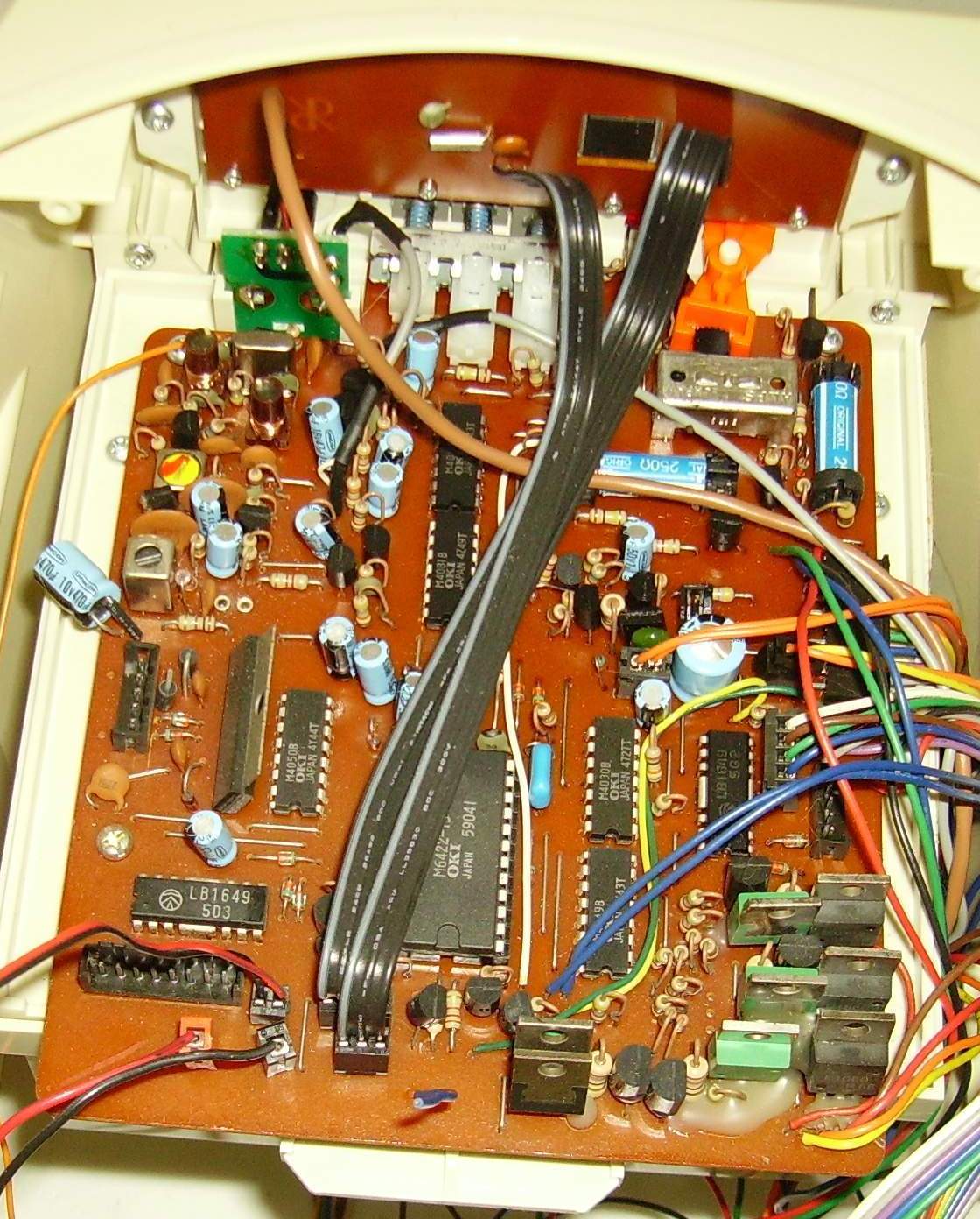
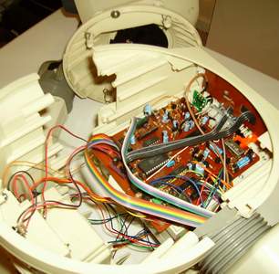
14. The robot back is still attached to the front. You have to un-plug the front housing from the back housing by disconnecting the remaining wires. Take special care in disconnecting the clock wires for these are push in connectors and it is easy to damage them.
* ( ANTENNA - If your robot has a back antenna you have to detach it at this stage.) |
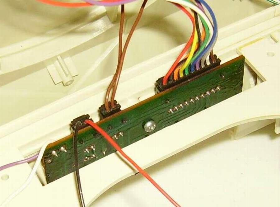
| Failure in properly remove the wires can result in damage to the connector and it will have to be replaced.
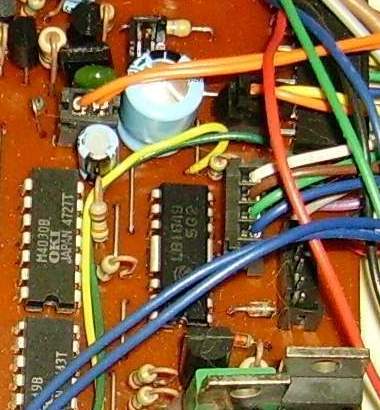
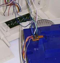
The following figures are pictures of the connectors in the robot.
 |
 |
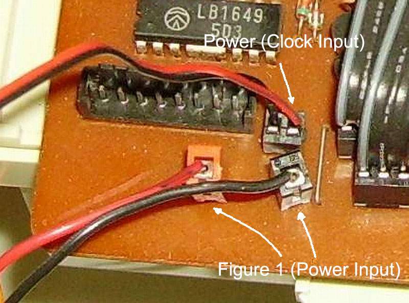
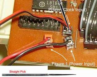
14a. The following connectors has some unique problems. The power input socket must be raised to remove the wire. (Failure to raise the connector to unlock it will result in damage to the connector and it will have to be replaced.)
1. Raise the Red/Black input sockets.(The socket will raise about 1/4") Do not force it.
2. Remove the wires. |
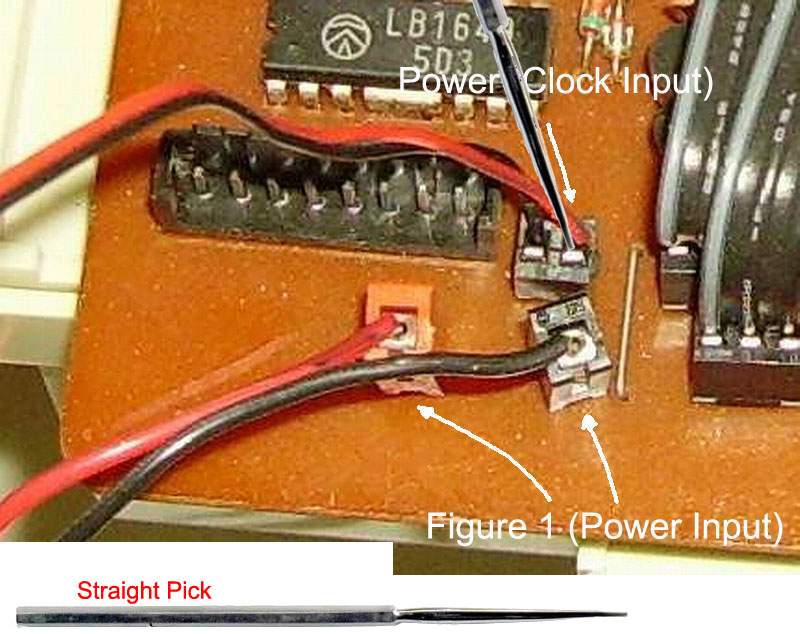
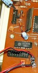
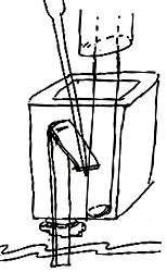
14b. The clock power input wires connector is a (one way, one time) wire push-in connector. There is a way to unlock the connector, but failure will result in in damage to the connector and it will have to be replaced.
 |
 |
There is a 80% chance that this will work depending on how gentle and accurate you are, and the connector itself. (Yes eight out of ten times I have been successful, but remember the other 20%) You will also need a Dental pick to remove the wires from the socket.
1. Insert the dental pick next to the wire and gently (very little pressure) press the wire down a touch, and rotating the wire gently pull it out. You might have to do this more than once but do not jam the dental pick in the socket. This will bend the contact and destroy the socket.
2. Repeat the process on the other wire. |
14c. The other connectors have normal plugs and sockets that are keyed. Remember how they are positioned and record it for you will have to assemble the robot later.
|
15. Push the one plug and harness to the outside of the robot. Push the other two plugs and harness to the inside of the robot. With all of the plugs and harness clear from the rear door, remove the rear door. |
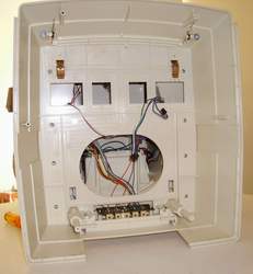
16. Separate the back housing from the front housing. |
 |
 |
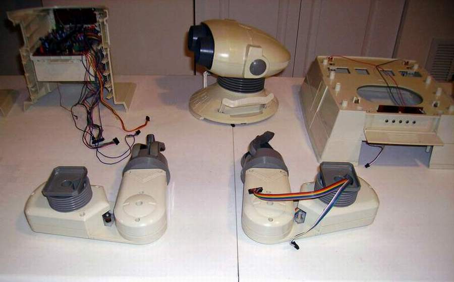
17. You have now disassembled the major components of the robot. Disassembly of the components will be addressed seperately. To reassemble the robot reverse the procedure.
18. The next step is the ressembly of the robot with the additional Left Arm Kit for controll of the Left Arm. |
|
| Omnibot ®2000 - Arm Circuit Board Installation & Assembly Procedure |
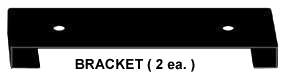
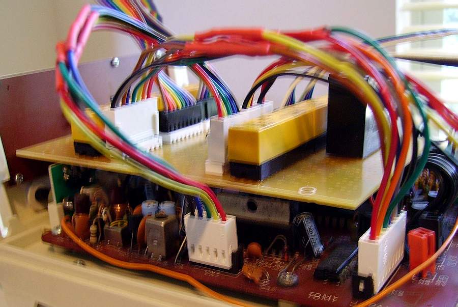
19. Add the brackets to the Arm Control Circuit Board. |
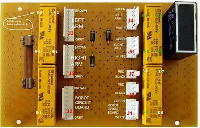 Motorized Arms Control Circuit Board
The direction of the installed relays is critical to the operation
Note: the bar on the relay is facing up toward the other relay The Left arm and right arm harness CANNOT be interchanged and must be plugged into the proper socket |
 |
|
 |
20. Solder the B+ and B- wires to the rear panel. |
|
21. Reinstall the door. Push the one plug and harness to the inside of the robot. Push the other two plugs and harness to the outside of the robot. With all of the plugs and harness installed from the rear door, you are ready to marry the robot body together. |
22. Add the Left and Right arms to the robot body and cearfull temperory close and secure it. * ( ANTENNA - If your robot has a back antenna you can attach it at this stage.) |
23. Add the robot head to the robot. Plug in all of the plugs to the mother board. At this time add the extension cables to the Arm Circuit Board.. |
* ( ANTENNA - If your robot has a base antenna you have to attach it at this stage.)
|
27. Install the wires and plugs that go to the external Jacks board on the base housing from the robot.
28. Install the base housing from the robot. |
29. Install the screws from the base housing of the robot. Install the base housing to the robot, turn it and lay it flat on the table. |
30. Turn the base and plug the three plugs from the drive box that go to the robot. Make sure that you place them properly. Complete 30 a & 30 b below before mounting. |

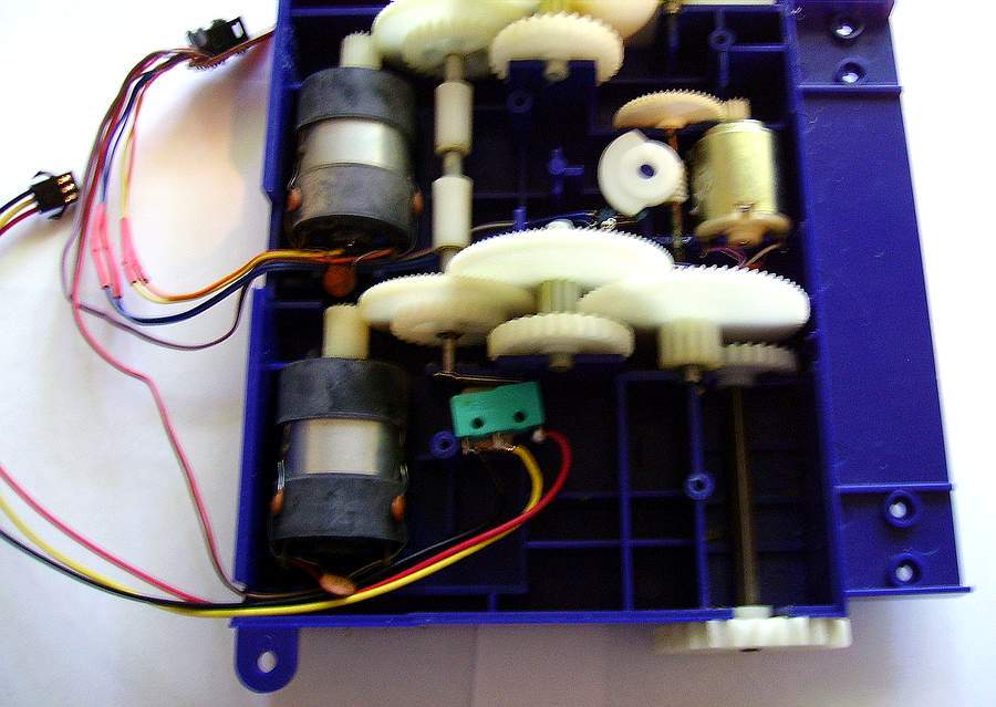
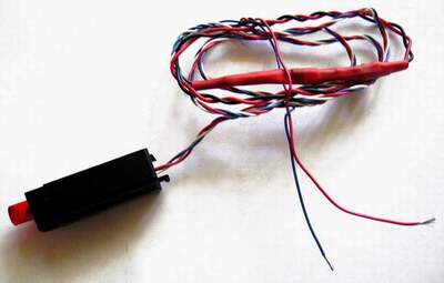
30 a. Mount the Control Switch In The Motor Assembly |
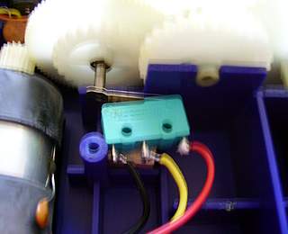
30 b. Mount the Control Switch In The Motor Assembly |
|
|
There is no warranty expressed or implied with this procedure. By using any information from this web site, you agree not to hold responsible this site, me, nor any of its representatives, for any injuries and/or damages, both physical and/or psychological, that may arise from the use and/or misuse of anything derived from this site. The user further agrees that such information/pictures does not constitute any guarantee of accuracy, safety or reliability, and that cannot be held responsible for any way. The user agrees to proceed at their own risk.
Source: My Collection - Updated 08-28-2008 |